- Categories
- Categories
- New & Hot Products
- Engine Swap Parts
- Categories / Engine Swap Parts
- Also in Engine Swap Parts
- Accessory Drive Brackets and Kits
- Exhaust Systems
- Gen III Hemi Swap Systems
- Mounts and Crossmembers
- Swap Accessories
- View All
- Marine and Powersports
- Categories / Marine and Powersports
- Also in Marine and Powersports
- Personal Watercraft
- Small Engine
- View All
- Air & Fuel Delivery
- Categories / Air & Fuel Delivery
- Also in Air & Fuel Delivery
- Air Cleaners
- Air Scoops
- Cold Air Intake
- Fuel System Kits
- Fuel Tanks and Fuel Cells
- HydraMat
- View All
- Exhaust
- Nitrous
- Categories / Nitrous
- Also in Nitrous
- Bottles and Accessories
- Controllers and Accessories
- Direct Port Systems
- Distribution Blocks, Filters, Adapters and Fittings
- Electrical and Wiring
- Fuel Pumps and Regulators
- Gauges
- Hose Lines and Tubing
- Intercooler Sprayers
- Microswitch and Solenoid Mounting Brackets
- NOS Jets
- Nitrous Blowdown Hoses and Tubes
- Nitrous Plates
- Nozzles
- Purge Kits
- Refill Kits and Components
- Solenoids and Solenoid Service Parts
- Tools
- View All
- Apparel & Collectibles
- Categories / Apparel & Collectibles
- Also in Apparel & Collectibles
- Backpacks
- Banners
- Clocks
- Decals
- Diecast
- Drinkware
- Face Masks & Gaiters
- Headwear
- Hitch Cover
- Hoodies
- Jackets
- Ladies Apparel
- Literature
- Metal Signs
- Misc
- Pet Accessories
- Polo Shirts
- Shop Shirt
- Sunglasses
- Tote Bags
- Youth Apparel
- View All
- Exterior
- Categories / Exterior
- Also in Exterior
- Convertible Tops and Components
- Decklid Panels
- Doors
- Fenders
- Firewall, Cowl, and Front Unibody
- Floor Pan and Frame
- Fuel Doors
- Graphic Kits
- Grilles
- Hood
- Lighting
- Mini Tub Kits
- Plate Frames and Accessories
- Quarter Panels
- Radiator Supports
- Rear Spoilers
- Rocker Panel
- Roof Panel
- Trim and Moldings
- Truck Bed & Parts
- Truck Cab & Parts
- Valances
- Weatherstrip
- Window and Windshield
- View All
- Off-Road
- AC and Heating
- Categories / AC and Heating
- Also in AC and Heating
- Controls and Cables
- Filler and Delete Panels
- Heater Box and Hoses
- Heater Core
- View All
- EV Conversions
- Categories / EV Conversions
- Also in EV Conversions
- Conversion Brackets and Accessories
- Displays
- High Voltage Contactors
- High Voltage Disconnects
- Power Distribution (PDU)
- Sensors, Connectors, and Accessories
- Vehicle Controls (VCU)
- Wiring Harnesses
- View All
- Plumbing AN Fittings and Hose
- Categories / Plumbing AN Fittings and Hose
- Also in Plumbing AN Fittings and Hose
- Adapters
- All Hose Groups
- Application Specific Parts
- Catch Tanks
- Fuel System Components
- Hose Ends
- Hose Protection, Sleeving & Clamps
- Mr Gasket Push-On
- Mr Gasket Swivel
- Oil & Cooling Systems
- Plumbing Tools
- Power Steering
- Premade Hoses
- Seals
- Super Stock
- Ultra Flex
- UltraPro
- Valves
- Weld-ons and Fill Caps
- View All
- Brakes
- Fasteners and Hardware
- Categories / Fasteners and Hardware
- Also in Fasteners and Hardware
- Quarter Turn Fasteners
- Safety Wire
- Transmission and Drivetrain
- Wheel and Tire
- View All
- Restoration
- Categories / Restoration
- Also in Restoration
- Air Conditioning and Heating
- Air and Fuel Delivery
- Books, Manuals & Brochures
- Brakes
- Bumper
- Convertible Tops and Components
- Cooling
- Decals Labels & Tags
- Electrical
- Engine & Transmission Mounting
- Exhaust
- Fender Covers
- Fuel Tanks & Components
- Ignition
- Lamps & Lighting
- Longbed to Shortbed Conversion Kits
- Radios & Stereos
- Suspension & Steering
- Trailer Hitches
- Transmission & Drivetrain
- Weatherstrip & Rubber
- Wheels & Accessories
- Windows & Windshield
- Wood Bed Floor and Trim
- View All
- Carburetors
- Gaskets
- Safety Equipment
- Categories / Safety Equipment
- Also in Safety Equipment
- Aprons
- Arm Restraints
- Chest and Rib Protectors
- Cleaners
- Drag Parachutes
- Equipment Bags
- Head and Neck Restraints
- Seats
- Shifter Boots
- Shoes
- Tow Straps
- Undergarments
- Window Nets
- Youth
- View All
- Cataclean
- Categories / Cataclean
- Gauges and Gauge Accessories
- Categories / Gauges and Gauge Accessories
- Also in Gauges and Gauge Accessories
- Gauge Accessories and Harnesses
- Gauge Adapters and Fittings
- Shift Lights
- Tach Adapters
- View All
- Suspension & Chassis
- Categories / Suspension & Chassis
- Also in Suspension & Chassis
- Air Ride
- Body Mounts and Hardware
- C-Notch Kits
- Driveshaft Safety Loops
- Front Drop Axles & Kingpins
- Hitches and Towing
- Leveling and Lift Kits
- Longbed to Shortbed Conversion Kits
- Roll Cage Kits
- Shocks and Struts
- Springs & Bumpstops
- Strut Tower and Chassis Braces
- Sway Bars and Components
- Traction Bars and Components
- View All
- Cooling
- Ignition
- Tools, Shop Equipment & Chemicals
- Categories / Tools, Shop Equipment & Chemicals
- Also in Tools, Shop Equipment & Chemicals
- Diagnostic Tools
- Engine Tools
- Extra Long Fender Covers
- Fender Covers
- Fluid Tools
- Front End Covers
- Hand Tools
- Jumbo Fender Covers
- Oils, Fluids, & Additives
- Paint & Dye
- Shop Tools
- Trailer Tools
- View All
- Data Acquisition
- Categories / Data Acquisition
- Also in Data Acquisition
- Cables
- Modules
- Power Distribution Modules
- Sensors
- Sensors With Modules
- Wiring Accessories
- View All
- Intake Manifolds
- Categories / Intake Manifolds
- Carbureted Intake Manifolds
- Carburetor and Manifold Combos
- EFI Intake Manifolds
- Installation Parts and Accessories
Also in Intake Manifolds- Roots Supercharger Intake Manifolds
- View All
- Transmission & Drivetrain
- Categories / Transmission & Drivetrain
- Also in Transmission & Drivetrain
- Internal Components
- Rear Axle & Differential
- Transmission Controller
- Transmission Coolers
- Transmission Mounts
- Transmission Pans and Dipsticks
- Transmission Swap Parts
- Transmissions
- View All
- EFI - Fuel Injection
- Categories / EFI - Fuel Injection
- Also in EFI - Fuel Injection
- AEM EFI
- Atomic EFI
- EFI Distributors
- EFI Fuel System Components
- Gauges and Displays
- Harnesses
- Hilborn EFI and MFI Systems
- Hilborn Service Components
- Injectors
- Legacy EFI
- Modules and Sensors
- Terminator EFI
- Throttle Bodies
- Wiring Shop
- View All
- Interior
- Tuners and Programmers
- Categories / Tuners and Programmers
- Also in Tuners and Programmers
- Accessories
- Amp'd Throttle Booster
- Dinan Software-Tuning
- Inline Tuning Modules
- PCM
- View All
- Electrical
- Lighting
- Categories / Lighting
- Also in Lighting
- Bezels and Trim
- LED Light Bars
- LED Work Lights
- Marker and Signal Lamps
- Tail Lights
- View All
- Wheels and Wheel Accessories
- Categories / Wheels and Wheel Accessories
- Engine
- LS Power
- Categories / LS Power
- Also in LS Power
- EFI Components
- Engine and Transmission mounts
- Fuel Pump Regulator and Filter
- Fuel Tanks
- LS Accessory Drive Brackets and Kits
- LS Drivetrain
- LS Engine Components
- LS Gaskets
- LS Ignition Products
- LS Swap Oil Pans
- LS Swap Radiators
- LS Throttle Bodies
- LS Tools
- LS Valve Covers & Engine Appearance
- LS and LT Nitrous Systems
- View All
-
- Brands
- Brands
- ACCEL
- DiabloSport
- Holley RetroBright
- REKUDO
- ADS
- Dinan
- Hooker
- REV Wheels
- AEM
- Drake Muscle Cars
- Hooker BlackHeart
- Rocket Racing Wheels
- AEM EV
- Earl's
- Hurst
- Scott Drake
- Amp'd
- Edge
- Lakewood
- Simpson Motorcycle
- Anvil Off-Road
- Fender Gripper
- Legendary Wheels
- Simpson Racing
- APR
- Flowmaster
- Mallory
- Sniper
- B&M
- Flowmonster
- Mr. Gasket
- SPAL Fans
- Baer Brakes
- Flowtech Exhaust
- MSD
- Speartech
- Brawler
- Frostbite Cooling
- NOS
- Stilo
- Bright Earth
- Garrett Turbochargers
- ProConnect
- Street Fire
- Brothers Trucks
- Halibrand
- Proforged
- Superchips
- Carroll Shelby Wheels
- HANS
- Pulsar
- Weiand
- CataClean
- Hays
- Quick Fuel Technology
- White Box
- Classic Instruments
- Hilborn
- Quick Time
- XDR
- Demon
- HK Wheels
- Racepak
-
- Detroit Speed
- Holley
- RaceQuip
-
- DeWitts
- Holley EFI
- Range Technology
-
- Shop By Vehicle
- Shop By Vehicle
- Deals
Troubleshooting Techniques
- Checking The MSD Ignition For Spark
- Engine Run On
- Import Vehicles
- Magnetic Pickup in the distributor
- Modifying AMC oiling for performance
- No 12v present at Coil+
- Non-Magnetic Pickup Reistance Values
- Spark Plug Wires
- Timing Fluctuations
- Tachometer Operation
Checking The MSD Ignition For Spark
Checking The MSD Ignition For Spark
The following test will determine if your MSD is producing a spark.


White Wire Trigger:
If you are using the White wire (points or electronic amplifier) of the MSD to trigger the ignition, follow these steps.
- Make sure the ignition switch is in the Off position.
- Remove the coil wire from the distributor cap and position the terminal so it is approximately 1/2" from a good ground.
- Disconnect the MSD White wire from the distributor points or the ignition amplifier.
- Turn the ignition to the On position. DO NOT CRANK THE ENGINE.
- Tap the White wire to ground several times. Each time the wire is pulled away from ground a spark should jump from the coil wire to ground. If spark is present, the ignition is working properly.
If there is no spark:
- Inspect all of the wiring.
- Substitute another coil and test again. If there is now spark, the coil is at fault.
- If there is still no spark, check to make sure there is 12 volts on the small Red wire from the MSD when the key is in the On position. If 12 volts are not present, find another 12 volt source and repeat the test.
- After inspecting the test procedures and inspecting all of the wiring, there is still no spark, the Ignition is at fault. See the Warranty and Service Page for Information.
Magnetic Pickup Trigger:
If you are using the 2-Pin Magnetic Pickup of the MSD to trigger the ignition, follow these steps.
- Make sure the ignition switch is in the Off position.
- Remove the coil wire from the distributor cap and position the terminal so it is approximately 1/2" from a good ground.
- Disconnect the MSD Magnetic Pickup connector from the distributor.
- Turn the ignition to the On position. DO NOT CRANK THE ENGINE.
- With a small jumper wire, short the Green and Violet magnetic pickup wires together then pull the jumper off. Each time the short is removed a spark should jump If spark is present, the ignition is working properly.
If there is no spark:
- Inspect all of the wiring.
- Substitute another coil and test again. If there is now spark, the coil is at fault.
- If there is still no spark, check to make sure there is 12 volts on the small Red wire from the MSD when the key is in the On position. If 12 volts are not present, find another 12 volt source and repeat the test.
- After inspecting the test procedures and inspecting all of the wiring, there is still no spark, the Ignition is at fault. See the Warranty and Service Page for Information.
No 12v present at Coil +
- One common question in regards to MSD Ignition controls is “Why isn’t 12V power on the orange (COIL +) wire?”
The main reason 12V won’t be present at coil + is because your MSD ignition is a Capacitive Discharge Ignition. Like all CD ignitions they use a large capacitor to discharge 420-480 Volts to coil + and coil – will normally be connected to ground. (That’s why you wont see +12V on coil +) - Most all stock ignitions are Inductive Ignitions, these will normally be connected to the + 12V ignition switch to coil + and coil – is connected to Points or the Factory Electronic Module. (That’s why you’ll see +12V on coil +)
Engine Run On
Engine Run On
If your engine continues to run even when the ignition is turned Off you are experiencing engine Run-On. This usually only occurs on older vehicles with an external voltage regulator. Because the MSD receives power directly from the battery, it does not require much current to keep the unit energized. If you are experiencing run-on, it is due to a small amount of voltage going through the charging lamp indicator and feeding the small Red wire even if the key is turned off.

Early Ford and GM: To solve the Run-On problem, a Diode is supplied with the MSD in the parts bag. By installing this Diode in-line of the wire that goes to the Charging indicator, the voltage is kept from entering the MSD. The diagram below shows the proper installation for early Ford and GM vehicles.

Import Vehicles
Import Vehicles
If your fuel injected import vehicle fails to start or the tachometer reads erratically, you will need an MSD Tach Adapter PN 8910. If the PN 8910 is installed and you have spark but the vehicle will still not run, you will need a special Tach Adapter. Contact MSD Tech for the correct Adapter.
In some instances, after installing an MSD Ignition control unit on an import vehicle may result in a no-start situation or a erratic tach. Depending on which MSD Ignition was installed on the vehicle a tach adapter will be required to remedy the situation.
A no-start situation may result from a smart ECU not sensing coil current as a result not energizing the Fuel pump. The 8912 tach adapter will develop an artificial coil current to sadisfy the Smart ECU’s requirement to energize the Fuel pump again.
An erratic tach or non working tach is a result of the factory wire being removed from the coil -. The adapter will also develop a tach signal to satisfy the tach again.
If a DIS controller was installed, a PN 8912 will be required.

Installation to an MSD DIS-4 using Three Channels
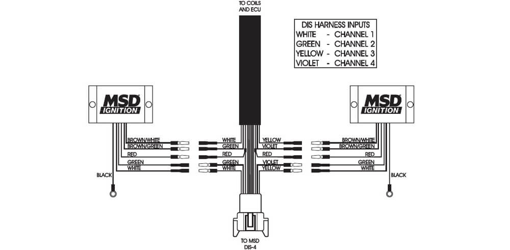
Installation to an MSD DIS-4 Ignition using Four Channels. If a 6 series, 7 series, or SCI ignition was installed, a PN 8910-EIS will be required.
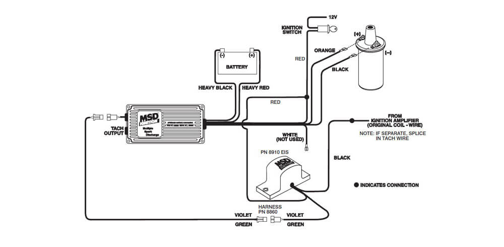
Wiring the Tach Adapter PN 8910 EIS
Magnetic Pickup in the distributor
Magnetic Pickup in the distributor
The magnetic pickup in MSD Distributors can also be checked with an Ohm meter to make sure it is within operating specifications. Once again, connect the Ohm meter's leads to the two terminals of the pickup. The resistance should be within 500 - 700 ohms. If the resistance is out of this specification, inspect the condition of the wires leading to the pickup for abrasion, shorting or opens. If the wiring is okay, the pickup is at fault.
NOTE: The Ignition will check good if the pickup is at fault. Follow the Checking for Spark procedure.

Modifying AMC oiling for performance
Modifying AMC oiling for performance
An age old hot rodding adage goes something like: “An engine is more than the sum of its parts”. While that oft-repeated saying has been tossed around so much as to be threadbare, that doesn’t make it any less true. Details are key, and are what separate two otherwise identical engines. Many enthusiasts are so focused on choosing parts that they sometimes overlook little things in assembly that will improve their engine’s durability as well as its performance.
One example is careful preparation of the oiling system. They may believe the factory knew what it was doing when it designed the engine, so they see no need to mess with it. What they fail to take into account is manufacturing tolerances and things like core shift during the casting process. They also may be overlooking the fact that they are asking far more of their engine than the manufacturer had intended it to provide.
American Motors enthusiasts know that their marquee’s V8 engines have a unique oiling system that requires special consideration. These engines supply oil to the distributor gear last and via a circuitous path, which needs careful preparation to ensure adequate oil flow. There are several key areas to focus your attention, and we will highlight each of them in this story. This discussion applies to AMC’s from 1967 and on: 290, 304, 343, 360, 390, and 401 cubic inch varieties.
Follow along as we outline the trouble spots in the AMC V8’s distributor lubrication scheme and show you how to counteract them. A little extra attention given to the oiling system with these simple modifications during your next build will pay big dividends down the road.
- When performing final engine assembly, the first critical point is the front camshaft bearing orientation. Placement of this bearing requires precise alignment of the bearings’ oil feed hole with the block’s oil gallery. This ensures maximum oil flow to the camshaft’s front journal groove. The groove must completely encircle the journal in order to ensure proper lubrication throughout the camshaft rotation.
- There is a single bore in the front camshaft bearing journal groove that exits on the front face of the journal. This in turn feeds a groove in the rear of the cam timing sprocket. Be sure that the cam bearing or bearing journal (or both) is grooved. This is absolutely critical to proper camshaft and timing gear lubrication.
- Looking at the back side of the cam timing sprocket, make sure this groove lines up with the hole in the front of the camshaft. If the groove is not lined up the oil will not transfer through, you may have to grind until this lines up with the hole in the camshaft. The oil moves down the groove to a chamfer at the center bore then to a passage adjacent to the keyway. This passage is typically quite rough and benefits greatly from some clean up with a small file to minimize oil flow restriction.
- On the front of the cam timing sprocket is another chamfer, along with six small grooves on the face of this surface. These grooves redirect a small amount of oil to the timing chain and the fuel pump eccentric.
- From the timing sprocket, the oil continues on through the passage in the fuel pump eccentric adjacent to the keyway, and then to the distributor drive gear.
- The distributor drive gear has four holes amongst the gear teeth where pressurized oil is fed to the distributor gear.
- When this gear is installed, it is critical that these holes are not obstructed by the camshaft snout. The camshaft to the end of the gear has an open area so oil can feed through these holes.
- The camshaft retaining bolt and washer serve a dual purpose. Their installed height is important as they constitute the camshaft thrust button.
- Additionally, the diameter of the washer is critical as it seals the end of the distributor drive gear; forcing lubricant through the distributor drive gear’s oiling holes.
- There are some aftermarket front covers in circulation that also contribute to distributor gear failure. Before final assembly of the engine, test fit the distributor, oil pump gear and cover. With the distributor completely seated without the gasket in the oil pump shaft, and the pump gear fully seated in its housing, check to see if the distributor flange is seated against the top of the cover or if a gap exists, as shown.
- The distributor should bottom out in the front cover with no gasket when the oil pump is installed, if distributor does not bottom on the cover there could be a timing cover problem or the oil pump shaft groove depth issue. It could be the radius on the bottom of the oil pump groove to large, in which you can clean this with a file to get the proper fit.
- When installing the timing cover during final assembly, do not overlook installation of the dowel pins in the block. These will insure proper cover alignment.
- After installing the cover to the engine, install and test fit the distributor. Note, when installing the distributor, it should slide easily into place. If not, there may be an alignment issue, one of the Timing cover manufactures had issues with alignment of this cover and depth of the oil pump and distributor, this would cause the distributor to bind as it was installed and cause gear failure.
- At this point of the engine assembly, you should verify the distributor gear will be sufficiently lubricated. This can be observed through the fuel pump mounting hole. Using an oil pump priming tool, look for oil streaming around the outside of the distributor drive gear. Additionally, you should rotate the crankshaft and be sure this oil stream continues for two revolutions of the crank.
- When these procedures are completed install the distributor
- Note, the use of racing oil will help the gears break in. This type oil has zinc which the oil manufactures removed from standard automotive oils. The zinc will help the gears mate.

No 12v present at Coil+
Non-Magnetic Pickup Reistance Values
Spark Plug Wires
Timing Fluctuations
Tachometer Operation
Tachometer Operation
If your tachometer doesn't read correctly after installing an MSD, you may need a Tach Adapter. On GM vehicles, first remove the tach filter. There are two MSD Tach Adapters. The chart below displays the most common Tach Adapter options:
| Aftermarket Tachometers | White Wire Trigger | Magnetic Trigger Connector |
|---|---|---|
| Autogage | 8910 | 8920 |
| Autometer | None | None |
| Classic | 8910 | 8920 |
| Dixco | 8910 | 8920 |
| Faria | 8910 | 8920 |
| Ford Motorsports | None | None |
| Mallory | None | None |
| Medallion | 8910 | 8920 |
| Moroso | None | None |
| Stewart Warner | 8910 | 8920 |
| S.W. & Bi Torx | None | None |
| Sun | 8910 | 8920 |
| Veglia Borletti | 8910 | 8920 |
| VDO | 8910 | 8920 |
| Factory Tachometers | White Wire Trigger | Magnetic Trigger Connector |
| AMC (Jeep) | See Note #1 - 8910 | See Note #1 - 8920 |
| Chrysler | 8910 | 8920 |
| Ford (Before 1976) | See Note #1 - 8910 | See Note #1 - 8920 |
| Ford (After 1976) | See Note #2 - 8910 | See Note #2 - 8920 |
| General Motors | See Note #3 | See Note #3 |
| Imports | See Note #1 - 8910 | See Note #1 - 8920 |
On the chart above, the trigger wire on tachometers that are marked None may be connedted to the Tach Output Terminal on the MSD 6 Series Ignition Unit using the supplied Female Faston Receptacle.

The diagram above shows a typical wiring schematic for aftermarket tachometers. These tachometers will usually have three wires and sometimes a fourth for a panel light.
Note #1: There are basically two types of tachometers: Current Triggered Tachometers and Voltage Triggered Tachometers. These type of tachometer that is on the vehicle may be recognized by the way it is connected to the ignition coil. The drawings below show two wiring diagrams to help in determining which type of tachometer is on the vehicle.

Note #2:These auto manufacturers use tachometers made by different tachometer manufacturers. Some will work when connected to the MSD 6 Series Ignition Unit Tach Output Terminal. Otherse may require an MSD Tach Adapter. Connect the tachometer trigger wire to the Tach Output Terminal as shown below to determine if the tachometer is operating correctly. If it does not operate correctly, go back to the Chart to determine which MSD Tach Adapter should be used.
Tachometer Trigger Wire - This is the wire that went from the Tachometer to the Negative side of the coil. Remove the end of the wire that is connected to the coil and connect it to the MSD Tach Output Terminal as shown:

Note #3:General Motors Corporation vehicles have an inline filter that should be bypassed when the factory tachometer drops back to zero as the engine RPM is going up. The drawings at the right show what the filter might look like. Located the filter by tracing the wire from the Tach Terminal on Vehicles equipped with an HEI Ignition system. On vehicles equipped without an HEI, trace the wire from the coil negative terminal until the filter is found. Disconnect both wires from the filter and leave disconnected. Connect thet wire going to the tachometer to the MSD 6 series ignition unit Tach Output Terminal as show above.
Note #4:If the Tachometer is connected to the positive side of the ignition coil, do not attempt to connect this tachometer to the tach ouput terminal on the MSD 6 series unit.

See Note #1 for a diagram of a current triggered tach. The tachometer is connected to the positive side of the ignition coil. The ballast resistor or resistance wire can be on either side of the coil.


 Get help from other Gear Heads!


Back To Top