- Categories
- Categories
- New & Hot Products
- Engine Swap Parts
- Categories / Engine Swap Parts
- Also in Engine Swap Parts
- Accessory Drive Brackets and Kits
- Exhaust Systems
- Gen III Hemi Swap Systems
- Mounts and Crossmembers
- Swap Accessories
- View All
- Marine and Powersports
- Categories / Marine and Powersports
- Also in Marine and Powersports
- Personal Watercraft
- Small Engine
- View All
- Air & Fuel Delivery
- Categories / Air & Fuel Delivery
- Also in Air & Fuel Delivery
- Air Cleaners
- Air Scoops
- Cold Air Intake
- Fuel System Kits
- Fuel Tanks and Fuel Cells
- HydraMat
- View All
- Exhaust
- Nitrous
- Categories / Nitrous
- Also in Nitrous
- Bottles and Accessories
- Controllers and Accessories
- Direct Port Systems
- Distribution Blocks, Filters, Adapters and Fittings
- Electrical and Wiring
- Fuel Pumps and Regulators
- Gauges
- Hose Lines and Tubing
- Intercooler Sprayers
- Microswitch and Solenoid Mounting Brackets
- NOS Jets
- Nitrous Blowdown Hoses and Tubes
- Nitrous Plates
- Nozzles
- Purge Kits
- Refill Kits and Components
- Solenoids and Solenoid Service Parts
- Tools
- View All
- Apparel & Collectibles
- Categories / Apparel & Collectibles
- Also in Apparel & Collectibles
- Backpacks
- Banners
- Clocks
- Decals
- Diecast
- Drinkware
- Face Masks & Gaiters
- Headwear
- Hitch Cover
- Hoodies
- Jackets
- Ladies Apparel
- Literature
- Metal Signs
- Misc
- Pet Accessories
- Polo Shirts
- Shop Shirt
- Sunglasses
- Tote Bags
- Youth Apparel
- View All
- Exterior
- Categories / Exterior
- Also in Exterior
- Convertible Tops and Components
- Decklid Panels
- Doors
- Fenders
- Firewall, Cowl, and Front Unibody
- Floor Pan and Frame
- Fuel Doors
- Graphic Kits
- Grilles
- Hood
- Lighting
- Mini Tub Kits
- Plate Frames and Accessories
- Quarter Panels
- Radiator Supports
- Rear Spoilers
- Rocker Panel
- Roof Panel
- Trim and Moldings
- Truck Bed & Parts
- Truck Cab & Parts
- Valances
- Weatherstrip
- Window and Windshield
- View All
- Off-Road
- AC and Heating
- Categories / AC and Heating
- Also in AC and Heating
- Controls and Cables
- Filler and Delete Panels
- Heater Box and Hoses
- Heater Core
- View All
- EV Conversions
- Categories / EV Conversions
- Also in EV Conversions
- Conversion Brackets and Accessories
- Displays
- High Voltage Contactors
- High Voltage Disconnects
- Power Distribution (PDU)
- Sensors, Connectors, and Accessories
- Vehicle Controls (VCU)
- Wiring Harnesses
- View All
- Plumbing AN Fittings and Hose
- Categories / Plumbing AN Fittings and Hose
- Also in Plumbing AN Fittings and Hose
- Adapters
- All Hose Groups
- Application Specific Parts
- Catch Tanks
- Fuel System Components
- Hose Ends
- Hose Protection, Sleeving & Clamps
- Mr Gasket Push-On
- Mr Gasket Swivel
- Oil & Cooling Systems
- Plumbing Tools
- Power Steering
- Premade Hoses
- Seals
- Super Stock
- Ultra Flex
- UltraPro
- Valves
- Weld-ons and Fill Caps
- View All
- Brakes
- Fasteners and Hardware
- Categories / Fasteners and Hardware
- Also in Fasteners and Hardware
- Quarter Turn Fasteners
- Safety Wire
- Transmission and Drivetrain
- Wheel and Tire
- View All
- Restoration
- Categories / Restoration
- Also in Restoration
- Air Conditioning and Heating
- Air and Fuel Delivery
- Books, Manuals & Brochures
- Brakes
- Bumper
- Convertible Tops and Components
- Cooling
- Decals Labels & Tags
- Electrical
- Engine & Transmission Mounting
- Exhaust
- Fender Covers
- Fuel Tanks & Components
- Ignition
- Lamps & Lighting
- Longbed to Shortbed Conversion Kits
- Radios & Stereos
- Suspension & Steering
- Trailer Hitches
- Transmission & Drivetrain
- Weatherstrip & Rubber
- Wheels & Accessories
- Windows & Windshield
- Wood Bed Floor and Trim
- View All
- Carburetors
- Gaskets
- Safety Equipment
- Categories / Safety Equipment
- Also in Safety Equipment
- Aprons
- Arm Restraints
- Chest and Rib Protectors
- Cleaners
- Drag Parachutes
- Equipment Bags
- Head and Neck Restraints
- Seats
- Shifter Boots
- Shoes
- Tow Straps
- Undergarments
- Window Nets
- Youth
- View All
- Cataclean
- Categories / Cataclean
- Gauges and Gauge Accessories
- Categories / Gauges and Gauge Accessories
- Also in Gauges and Gauge Accessories
- Gauge Accessories and Harnesses
- Gauge Adapters and Fittings
- Shift Lights
- Tach Adapters
- View All
- Suspension & Chassis
- Categories / Suspension & Chassis
- Also in Suspension & Chassis
- Air Ride
- Body Mounts and Hardware
- C-Notch Kits
- Driveshaft Safety Loops
- Front Drop Axles & Kingpins
- Hitches and Towing
- Leveling and Lift Kits
- Longbed to Shortbed Conversion Kits
- Roll Cage Kits
- Shocks and Struts
- Springs & Bumpstops
- Strut Tower and Chassis Braces
- Sway Bars and Components
- Traction Bars and Components
- View All
- Cooling
- Ignition
- Tools, Shop Equipment & Chemicals
- Categories / Tools, Shop Equipment & Chemicals
- Also in Tools, Shop Equipment & Chemicals
- Diagnostic Tools
- Engine Tools
- Extra Long Fender Covers
- Fender Covers
- Fluid Tools
- Front End Covers
- Hand Tools
- Jumbo Fender Covers
- Oils, Fluids, & Additives
- Paint & Dye
- Shop Tools
- Trailer Tools
- View All
- Data Acquisition
- Categories / Data Acquisition
- Also in Data Acquisition
- Cables
- Modules
- Power Distribution Modules
- Sensors
- Sensors With Modules
- Wiring Accessories
- View All
- Intake Manifolds
- Categories / Intake Manifolds
- Carbureted Intake Manifolds
- Carburetor and Manifold Combos
- EFI Intake Manifolds
- Installation Parts and Accessories
Also in Intake Manifolds- Roots Supercharger Intake Manifolds
- View All
- Transmission & Drivetrain
- Categories / Transmission & Drivetrain
- Also in Transmission & Drivetrain
- Internal Components
- Rear Axle & Differential
- Transmission Controller
- Transmission Coolers
- Transmission Mounts
- Transmission Pans and Dipsticks
- Transmission Swap Parts
- Transmissions
- View All
- EFI - Fuel Injection
- Categories / EFI - Fuel Injection
- Also in EFI - Fuel Injection
- AEM EFI
- Atomic EFI
- EFI Distributors
- EFI Fuel System Components
- Gauges and Displays
- Harnesses
- Hilborn EFI and MFI Systems
- Hilborn Service Components
- Injectors
- Legacy EFI
- Modules and Sensors
- Terminator EFI
- Throttle Bodies
- Wiring Shop
- View All
- Interior
- Tuners and Programmers
- Categories / Tuners and Programmers
- Also in Tuners and Programmers
- Accessories
- Amp'd Throttle Booster
- Dinan Software-Tuning
- Inline Tuning Modules
- PCM
- View All
- Electrical
- Lighting
- Categories / Lighting
- Also in Lighting
- Bezels and Trim
- LED Light Bars
- LED Work Lights
- Marker and Signal Lamps
- Tail Lights
- View All
- Wheels and Wheel Accessories
- Categories / Wheels and Wheel Accessories
- Engine
- LS Power
- Categories / LS Power
- Also in LS Power
- EFI Components
- Engine and Transmission mounts
- Fuel Pump Regulator and Filter
- Fuel Tanks
- LS Accessory Drive Brackets and Kits
- LS Drivetrain
- LS Engine Components
- LS Gaskets
- LS Ignition Products
- LS Swap Oil Pans
- LS Swap Radiators
- LS Throttle Bodies
- LS Tools
- LS Valve Covers & Engine Appearance
- LS and LT Nitrous Systems
- View All
-
- Brands
- Brands
- ACCEL
- DiabloSport
- Holley RetroBright
- REKUDO
- ADS
- Dinan
- Hooker
- REV Wheels
- AEM
- Drake Muscle Cars
- Hooker BlackHeart
- Rocket Racing Wheels
- AEM EV
- Earl's
- Hurst
- Scott Drake
- Amp'd
- Edge
- Lakewood
- Simpson Motorcycle
- Anvil Off-Road
- Fender Gripper
- Legendary Wheels
- Simpson Racing
- APR
- Flowmaster
- Mallory
- Sniper
- B&M
- Flowmonster
- Mr. Gasket
- SPAL Fans
- Baer Brakes
- Flowtech Exhaust
- MSD
- Speartech
- Brawler
- Frostbite Cooling
- NOS
- Stilo
- Bright Earth
- Garrett Turbochargers
- ProConnect
- Street Fire
- Brothers Trucks
- Halibrand
- Proforged
- Superchips
- Carroll Shelby Wheels
- HANS
- Pulsar
- Weiand
- CataClean
- Hays
- Quick Fuel Technology
- White Box
- Classic Instruments
- Hilborn
- Quick Time
- XDR
- Demon
- HK Wheels
- Racepak
-
- Detroit Speed
- Holley
- RaceQuip
-
- DeWitts
- Holley EFI
- Range Technology
-
- Shop By Vehicle
- Shop By Vehicle
- Deals
Ignition technical support
Technical Resources
Ignition Basics
See More
| Tech Notes |
|---|
|
Wiring Diagrams and Tech Notes
Provides over 150 pages of diagrams and details on MSD's ignition line Updated - 2014-01-01 |
|
|
| MSD View Software |
|---|
|
Driver Installation in Windows 8
Step-by-step instructions on driver installation in Windows 8 |
|
Driver Installation in Windows 8.1
Step-by-step instructions on driver installation in Windows 8.1 |
|
MSD View Software
MSD View version 4.5.8.exe Software for use with Power Grid System Updated - 2021-05-11 |
| MSD Pro-Data+/GraphView Software |
|---|
|
Driver Installation in Windows 8
Step-by-step instructions on driver installation in Windows 8 |
|
Driver Installation in Windows 8.1
Step-by-step instructions on driver installation in Windows 8.1 |
|
MSD GraphSave Software
View, modify and save user data for all MSD Digital Programmable products. |
|
MSD Pro-Data+ Software
MSD Pro-Data+ Software for use with all MSD Digital Programmable products. |
| Powersports Software |
|---|
|
Powersports Pro-Data+ Software
Powersports Pro-Data+ Software for use with Powersports Digital Programmable products. |
|
Powersports View Software
MSD View Software for use with for Powersports part numbers 4244, 4245, 4248 and 4247. |
| Application Guides |
|---|
|
MSD Spark Plug Dimensions
MSD spark plug dimensions reference guide. |
|
Spark Plug Cross Reference Guide
MSD Cross Reference with NGK® Stock Number to Plug Type |
|
Spark Plug Torque Specs
Recommended Spark Plug Torque Specifications |
|
Spark Plug Failure Guide
Quick Reference Plug Failure Guide |
|
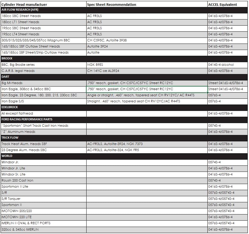
Spark Plug Application Guide
Spark Plug Application Guide for Aftermarket Cylinder Heads |
|
Spark Plug Terminal and Boot Attachment
Simple steps to follow while installing spark plug wires - Prevent Breakdowns Updated - 2011-12-01 |
|
MSD Spark Plug Application Guide
2014 SPARK PLUG CATALOG AND APPLICATION GUIDE Updated - 2014-01-01 |
How to test for spark on your MSD 6 Series
FAQ's
- What is the Test procedure for checking my Unilite electronic ignition module’s operation?
INSTRUCTIONS
- Remove both the distributor cap and rotor, then turn the ignition ON but DO NOT START car.
- Now connect your Red voltmeter wire to the NEGATIVE terminal (-) on the coil, by attaching the Red lead wire clip from voltmeter to the (-) terminal.
- Next attach your Black voltmeter wire to an engine ground on a good ground source. We suggest a manifold, or header bolt. Most anywhere on the engine is good.
- Now the voltage should read about 11 to 12 volts at this point. Remember to turn the key on for this reading! 12 volts must be present on your voltmeter.
- Next, place a credit card down into the distributor, blocking the 2 photo optic eyes on top the module facing each other on the top. With eyes blocked, the volts should drop way down below 2 volts or less. This drop is a must! If the voltage drops down to anything under 2 volts, then the module is good and ready to use. If the voltage does NOT drop, the module will need to be replaced.
- This damage could have been caused by many things, such as: power surge from an alternator, high resistance spark plugs and plug wires, improper ground wires, if someone has given you a jump, if you have given someone a jump, or battery chargers, which can also damage ignition modules. If voltage always stays below 2 volts and never increases up to 11-12 volts, then the module has been spiked by high voltage and needs to be replaced.
NOTE: The lack of a ballast resistor will cause this type of spike. If the voltage only drops down to 3-4 volts, this will produce a weak spark: too weak to run engine and the module will need to be replaced.Helpful? - Where do I need to connect the 3 colored wires (Red, Green and Brown) on a Unilite distributor?The Green wire connects to the Negative (-) coil terminal. The Red wire connects to the Positive (+) coil terminal, and the Brown wire connects to a good engine ground. The brown wire must be ground to the engine.Helpful?
- What coil should I use for my Mallory Unilite distributor, and/or Mallory Hyfire CD ignition box?All Unilite distributors need coils with a minimum amount of 1.4 Ohms primary resistance. Coils are 12 volts; however, they do have different amounts of primary resistance, which is measured in Ohms. You can still use a coil with less than 1.4 Ohms, but you must install a Ballast Resistor (Mallory #700) between the coil and the distributor, install on Red wire coming out of the Unilite distributor. It is Important to know that the Unilite distributor will work initially on the engine with less than 1.4 Ohm, BUT NOT FOR LONG. It only takes a short period of time to burn up the module using a coil with the wrong resistance.
When you select a coil for any High power CD ignition box like the Mallory Hyfire CD boxes, the Mallory Hyfire CD boxes MUST always use a coil with LESS than 1 Ohm of primary resistance.Helpful? - What is the part number for the Unilite distributor replacement ignition module?There are two modules that are available. The first is Mallory part # 605, and the second is Mallory part # 6100M. Both come with a 1 year warranty.Helpful?
- Does Mallory sell an electronic distributor conversion kit to do away with my points set up?YES, there are two (2) choices of kits to choose from when purchasing our conversion kit. First, you will need to know what kind of distributor you have now. If it is a Mallory, we will need the Mallory Part number #. The kits are called "E-Spark" conversion kits or "Unilite" conversion kits.Helpful?
- Why is my Mallory electric fuel pump fluctuating in pressure and jumping all over?There are many things that could cause this issue. The top offenders include using the wrong size fuel pressure regulator, not using a return line, or having a return line that is too small. Other causes could include using too many 90° degree elbows, an improperly sized fuel pump is the wrong size for the engine Horsepower or using a return line out of the pump.Helpful?
- Can I buy parts like bushings, shafts & springs for my distributor and rebuild it myself?The only service parts available are Caps, Rotors, Modules, Gears, and Curve Kits. If you need more than this, you’ll need to send distributor to us, for a FREE estimate on a repair price. Please complete and include the repair form found on our site.Helpful?
- What is the Replacement Ignition Module and pick up coil for my Mallory HEI distributor?There are two types of Mallory HEI Distributors: 75 series and 85 series units. The 75 series HEI uses a Module with a Rev-limiter - Module Part #699. The 85 series HEI uses the Module Part #607.
NOTE: Pick-up coils for the HEI distributors are NOT available as replacement parts.Helpful? - What’s the part number for replacement cap and rotor on my Mallory Comp 9000 distributor?The Comp 9000 distributors is an older design that we sold prior to the UNILITE. The replacement cap and rotors are available for sale and must be bought to match the distributor part number #. If you contact us with your distributor part number we can match the cap and rotor to his Comp 9000 distributor.Helpful?
- What spark plug gap should I use when using the ACCEL HEI coil?.045 is a good starting point. Check your plugs after 100 miles of driving. The white porcelain around the electrode of a properly gapped plug should have khaki tan coloration. If the plugs look black, close the gap by .005 to .040. If the porcelain is white, open the gap by .005 to .050 to cool the operating temperature of the plug.Helpful?
- What is the difference between ACCEL coils PN 8140 and PN 8145ACC and should I use a ballast resistor?The ACCEL PN 8140 has 1.4 ohms primary resistance and will need a ballast resistor when used with a point style distributor. The ACCEL PN 8145ACC has 0.7 ohms primary resistance and will require a ballast resistor when used with a Mallory Unilite or Magnetic Breakerless Ignition Distributor.Helpful?
- Do I use a ballast resistor with ACCEL Super Coil #140001?Yes, you will need a ballast resistor when using ACCEL Super Coil #140001 with a Accel Points Conversion Kit, PN's 2010ACC, 2020, or Mallory Unilite or Magnetic Breakerless Ignition Distributor. To use with a points style distributor, additional resistance is needed to get to 3.0 OHMs.Helpful?
- How do you adjust the ACCEL distributor’s vacuum advance timing?Insert a 3/32 hex key into the vacuum port and turn clockwise to increase the advance. Turn counterclockwise to reduce the vacuum advance.Helpful?
- What ACCEL points eliminator kit do I need to convert an OEM point distributor to electronic?GM V8 1957-74: ACCEL PN 2010ACC Ford V8 1957-74: ACCEL PN 2020Helpful?
- What HEI distributor coil do you recommend for my ACCEL HEI unit?You will need to look at your original coil. If you have red and yellow OEM primary wires, use ACCEL #140003. If you have red and white OEM primary wires, use ACCEL #140005.Helpful?
- What ACCEL distributor will fit my GM Vortec V8?ACCEL # 59132, ACCEL Performance Distributor - 96-00 Chevy Vortec V-8Helpful?
- Where do I return my ACCEL Opti-Spark II broken distributor for exchange?Please refer to the “support” section of our website to fill out a repair form. https://www.holley.com/support/warranty/Helpful?
- How often should spark plug wires be replaced?Spark plug wires are a consumable item like oil in the engine, they should be changed on a frequent schedule that is determined by how often they run. A routine schedule of cleaning, inspecting and checking the resistance of the wires should be done as a routine maintenance program of the car. Some teams even keep a logbook of the resistance of when the wires were built to compare after running.
Some of the most common problems can come for the actual wire crimps that can be resolved by re-crimping the terminals or replacing the terminal. The terminals are designed as a conductor crimp so the conductor does not have to be bent over which fracture or damage the conductor making it can read a higher resistance than normal.
The resistance should be 40 to 50 ohms per foot once the measurement is noted that value should not change. The only other facture that cannot be checked is the outside jacket, other than cleaning and a visual inspection looking for abrasion, cuts and pinholes, the jacket will deteriorate in time due to the amount of energy being transferred through the wires.
The coil wire should be replaced often as it gets hit 8 times more than the other wires. Big budget teams replace wire set about every third race while most others would replace them every 6th to7th race. There really is no gauge as to how often to replace wire set. Remember the wires are the actual delivery system of the spark energy to the spark plug that will affect a performance of the engine if not up to par.Helpful? - How often should coils be replaced?This is a tough question to answer, there are only two reasons to replace coils when one is "Open" or has a shorted winding. In either case most can be found with a simple L.C.R. (Inductor, Capacitance and Resistance) meter. Notice that there are several numbers inscribed on the back of all coils.
One set is the date code (which had been changed to an easier method to read) and the second and third sets are the inductance values of the coils. In this case the numerical value does not represent any form of performance like 709 vs. 899 these numbers are simply inductance values of the windings. These numbers are used to monitor a change within the coil. Keep in mind that these numbers are relative to the meters being used, several variables can account for the values: coil temperature, lead length, and meter model and meter frequency output. So if you purchase an LCR meter these numbers will differ slightly from actual numbers on your coils. Once you acquire a meter it would be wise to log these values and periodically check them to see if they have changed. Theoretically, once a coil is built and has run successfully down the track it should never fail unless due to exterior damages.
In the beginning (1994) our coils were capable of extremely high voltages. The coils were capable of 55,000 volts to 60,000 volts as time passed we found that these voltage capabilities were unnecessary and were resulting in a high yield of coil failures prior to shipping. We redesigned the coils limiting the output voltages to 45,000 volts, this resulted in cooler running coils that were not capable of destroying themselves yielding higher percentages of higher quality coils.
Prior to purchasing a set of coils they have already met several of our quality benchmarks. One of the outstanding test is the coil must run for 5 minutes running at 1800 RPM without a coil wire attached, this test is performed 3 times before arriving the packaging department. This is to test the quality of the potting material, assuring that porosities or air bubbles are not present. In most cases if either are present the coil will fail prematurely. Eventually coil usage will degrade coil life or performance, unfortunately translating this into a number of passes, races or years is difficult to determine.Helpful? - What's the difference between a trigger from a magneto and a crank trigger?The main difference is the stability of timing in most cases the generators are driven by a drive system from the block in a single or dual configuration. To provide clearance the drives are designed with an offset driven by a belt arrangement or a set of gears. Belt stretch or backlash can affect timing accuracies as well as the cam to crank drive suffering from the same problem. This theory was unproven until RacePak developed their newest software that can monitor timing during a run.
Here we have a run showing the difference in timing in the generators vs. crank triggers. Notice how much the timing changes with the generator and how much smoother the timing is on the crank triggers. With the timing moving that much from base timing it explains the some of the catastrophic failures.Helpful? - What's the correct air gap on the crank trigger pick (Sensor)?This is a common question that is affected by other outside sources like:
Crank Trigger Wheel Diameter:
(Smaller vs. larger, larger being better because of higher magnet velocity)
Starter Type:
Block mounted vs. External (Blower Mounted)
Battery voltage:
12 Volts -24 volts (block mounted) 36 - 48 Volts (External starters)
Induction:
Blown vs. Non-Blown (Blower more engine drag especially when re-stripped)
All of the above will play a role as to what the proper air gap will be for that engine combination. Typical air gap should be between .040 to .080 the low side is deemed by crank flex and high side is hard starting to no start. If the engine fires up repeatedly, that can ensure the air gap is correct, and crank flex has been accounted for.
Air gap should not have a performance effect of the magneto system, however it has been noted that an excessive air gap can create a timing offset in the Race Pac data recorder by as much as 2º depending on the air gap.
Another solution to the problem can be a "Change Over Switch" that will allow starting with the generator and once started it can be switch to the crank trigger pickups. This can be done using a 4 pole, Double-Throw switch for a dual mag installation or a 2 Pole, Double-Throw switch for a single mag installation (See wiring diagrams*). A word of caution here, extending magnetic pickup leads can introduce EMI (Electro magnetic Interference) or RF (Radio Interference) into the system, this can cause random misfire and erratic timing, use at your desecration. Make sure to use a quality switch; most switches will cost $50 to $80 dollars DO NOT USE A CHEAP SWITCH! Also keep in mind that high vibration environments can cause switches to switch on and off during a run possibly resulting in engine damage.Helpful? - What's the minimum voltage requirement for the Pro Mag Timing Control?The minimum voltage will be 5.0 Volts to as high as 18.0 volts. Keep in mind that other devices connected to the battery (other than the Pro Mag Timing Retard and Six Shooter) like the air switches that can draw more current than the Pro Mag Timing Retard and Six Shooter. One good test would be to monitor the voltage with a meter and trigger the switches or timers via the WOT switch and watch the voltage.Helpful?
- Why does my tachometer jumps around on the rev-limiter?It sounds like the tachometer is connected to the 8132 Tach converter that is connected to the coil. When the Rev Limiter is active it randomly drops cylinder by not lighting certain cylinders. The coil then does not spark on those cylinders so the Tach converter does not generate a tach signal for the tachometer causing it to jump around.
One way to eliminate the tachometer jumping is the use of our Pro Mag Timing Retard that has a tach output. This unit will insure smooth tach trigger during Rev limiting because it not connected or depending on a coil signal.Helpful? - When should I replace my cap and rotor?Again these parts are a consumable item of the ignition system and the power level that we're running at these parts will wear and at a higher rate than accustom to than non MSD magneto products. Typical wear will have a burnt or worn edge that's not as crisp or sharp but should not hurt performance. The life of a cap and rotor on a 44-amp system will shorter vs a 12 or 20 amp system.Helpful?
- What's the correct air gap on the crank trigger pick (Sensor)?This is a common question that is affected by other outside sources like:
Crank Trigger Wheel Diameter:
(Smaller vs. larger, larger being better because of higher magnet velocity)
Starter Type:
Block mounted vs. External (Blower Mounted)
Battery voltage:
12 Volts -24 volts (block mounted) 36 - 48 Volts (External starters)
Induction:
Blown vs. Non-Blown (Blower more engine drag especially when re-stripped)
All of the above will play a role as to what the proper air gap will be for that engine combination. Typical air gap should be between .040 to .080 the low side is deemed by crank flex and high side is hard starting to no start. If the engine fires up repeatedly, that can ensure the air gap is correct, and crank flex has been accounted for.
Air gap should not have a performance effect of the magneto system, however it has been noted that an excessive air gap can create a timing offset in the Race Pac data recorder by as much as 2º depending on the air gap.
Another solution to the problem can be a "Change Over Switch" that will allow starting with the generator and once started it can be switch to the crank trigger pickups. This can be done using a 4 pole, Double-Throw switch for a dual mag installation or a 2 Pole, Double-Throw switch for a single mag installation (See wiring diagrams*). A word of caution here, extending magnetic pickup leads can introduce EMI (Electro magnetic Interference) or RF (Radio Interference) into the system, this can cause random misfire and erratic timing, use at your desecration. Make sure to use a quality switch; most switches will cost $50 to $80 dollars DO NOT USE A CHEAP SWITCH! Also keep in mind that high vibration environments can cause switches to switch on and off during a run possibly resulting in engine damage.Helpful? - How often should coils be replaced?This is a tough question to answer, there are only two reasons to replace coils when one is "Open" or has a shorted winding. In either case most can be found with a simple L.C.R. (Inductor, Capacitance and Resistance) meter. Notice that there are several numbers inscribed on the back of all coils.
One set is the date code (which had been changed to an easier method to read) and the second and third sets are the inductance values of the coils. In this case the numerical value does not represent any form of performance like 709 vs. 899 these numbers are simply inductance values of the windings. These numbers are used to monitor a change within the coil. Keep in mind that these numbers are relative to the meters being used, several variables can account for the values: coil temperature, lead length, and meter model and meter frequency output. So if you purchase an LCR meter these numbers will differ slightly from actual numbers on your coils. Once you acquire a meter it would be wise to log these values and periodically check them to see if they have changed. Theoretically, once a coil is built and has run successfully down the track it should never fail unless due to exterior damages.
In the beginning (1994) our coils were capable of extremely high voltages. The coils were capable of 55,000 volts to 60,000 volts as time passed we found that these voltage capabilities were unnecessary and were resulting in a high yield of coil failures prior to shipping. We redesigned the coils limiting the output voltages to 45,000 volts, this resulted in cooler running coils that were not capable of destroying themselves yielding higher percentages of higher quality coils.
Prior to purchasing a set of coils they have already met several of our quality benchmarks. One of the outstanding test is the coil must run for 5 minutes running at 1800 RPM without a coil wire attached, this test is performed 3 times before arriving the packaging department. This is to test the quality of the potting material, assuring that porosities or air bubbles are not present. In most cases if either are present the coil will fail prematurely. Eventually coil usage will degrade coil life or performance, unfortunately translating this into a number of passes, races or years is difficult to determine.Helpful? - Why can't I start my engine?In most cases it due to "Cranking RPM" or lack of RPM, the Pro Mags must see a minimum of 200 to 250 RPM to start. There are several variables that can contribute to a "NO Start" situation:
Starter type
Battery voltage
Newly re-striped blower*
Blower Overdrive
If Crank Triggered excessive Crank pickup air gap (See "What's the correct air gap on the crank trigger pick (Sensor)?")
Insure that the starter is of a Hi-Torque type and that the batteries are fully charged. Checking battery voltage while cranking will insure batteries are fully charged. In some cases 16 to 18volts can aid to a faster cranking speed. A word of caution: Not all starters can tolerate higher voltages and most block-mounted starters should not exceed 18Volts.
*A newly re-striped blower can have enough friction to lower the cranking speed, try spraying silicon spray to lubricate the rotors. If that doesn't do it remove the blower belt (For testing purposes) and check for spark, this should free the motor up enough that if you do get spark your cranking speed is too low to start the engine with the blower. If you do not get spark remove the spark plugs and crank the engine again (With the plugs removed the engine will spin quickly) if still no spark check the following:
Inspect all connectors to insure the pins have not back out and insure that the "grounds" are correct (see diagram) or call us. (915) 857-2785 in the Pro Mag Tech department. We can then walk you through several other steps.Helpful? - How can I trouble shoot my mag at the racetrack?There is several ways to trouble shoot the system in a "NO SPARK" situation:
- Is the rotor turning, something in the drive could have broken.
- Is the starter turning fast enough?
- Are the starter batteries fully charged?
- Has the blower been re-striped? Try silicone spray in the blower.
- Is the Kill switch stuck "closed"? Sometimes the contacts can arch or weld themselves closed. (Disconnect for test)
- Check the 4 pin connectors and pins to see if any of the pins have backed out of the connectors.
- If Crank triggered, check the crank pickup air gap it should be .030 to .080. Bypass the crank trigger pickup by connecting the two pin connectors on the side of the generator together and try restarting the engine, if it starts check the connections and cable for breaks.
- Check the pickup resistance with an ohm meter it should read:
- 3/8 pickup = 115 Ohms
- 3/4 pickup = 68 Ohms
- Internal pickup in the generator = 600 Ohms
Helpful? - Why can't I start my engine?In most cases it due to "Cranking RPM" or lack of RPM, the Pro Mags must see a minimum of 200 to 250 RPM to start. There are several variables that can contribute to a "NO Start" situation:
Starter type
Battery voltage
Newly re-striped blower*
Blower Overdrive
If Crank Triggered excessive Crank pickup air gap (See "What's the correct air gap on the crank trigger pick (Sensor)?")
Insure that the starter is of a Hi-Torque type and that the batteries are fully charged. Checking battery voltage while cranking will insure batteries are fully charged. In some cases 16 to 18volts can aid to a faster cranking speed. A word of caution: Not all starters can tolerate higher voltages and most block-mounted starters should not exceed 18Volts.
*A newly re-striped blower can have enough friction to lower the cranking speed, try spraying silicon spray to lubricate the rotors. If that doesn't do it remove the blower belt (For testing purposes) and check for spark, this should free the motor up enough that if you do get spark your cranking speed is too low to start the engine with the blower. If you do not get spark remove the spark plugs and crank the engine again (With the plugs removed the engine will spin quickly) if still no spark check the following:
Inspect all connectors to insure the pins have not back out and insure that the "grounds" are correct (see diagram) or call us. (915) 857-2785 in the Pro Mag Tech department. We can then walk you through several other steps.Helpful? - How can I trouble shoot my mag at the racetrack?There is several ways to trouble shoot the system in a "NO SPARK" situation:
- Is the rotor turning, something in the drive could have broken.
- Is the starter turning fast enough?
- Are the starter batteries fully charged?
- Has the blower been re-striped? Try silicone spray in the blower.
- Is the Kill switch stuck "closed"? Sometimes the contacts can arch or weld themselves closed. (Disconnect for test)
- Check the 4 pin connectors and pins to see if any of the pins have backed out of the connectors.
- If Crank triggered, check the crank pickup air gap it should be .030 to .080. Bypass the crank trigger pickup by connecting the two pin connectors on the side of the generator together and try restarting the engine, if it starts check the connections and cable for breaks.
- Check the pickup resistance with an ohm meter it should read:
- 3/8 pickup = 115 Ohms
- 3/4 pickup = 68 Ohms
- Internal pickup in the generator = 600 Ohms
Helpful? - What's the maximum amount of timing I can retard a Pro Mag system with a Timing Retard?The Pro Mag Timing Retard is 30º this s because of rotor phasing, any more than 30 degrees will result in a crossfire in the generator cap. Older Timing retard system that use retard chips are the same 30 degrees maximum.
The Pro Mag Timing Control was initially designed with a maximum of 15º of retard, but at the racers request we have pushed the unit to 30º of retard. By doing this the calibrations have changed slightly from 15º to 30º here are the values:
16º = 16º, 17º = 17º, 18º = 20º, 19º = 21º, 20º = 22º, 23º = 23º, 24º = 24º, 25º = 25º, 26º = 26º, 27º = 27º, 28º = 28º, 29º = 29º, 30º = 30º
These can be purchased at the MSD trailer only and are very limited supply. They only cost $8 eachHelpful? - How often should spark plug wires be replaced?Spark plug wires are a consumable item like oil in the engine, they should be changed on a frequent schedule that is determined by how often they run. A routine schedule of cleaning, inspecting and checking the resistance of the wires should be done as a routine maintenance program of the car. Some teams even keep a logbook of the resistance of when the wires were built to compare after running.
Some of the most common problems can come for the actual wire crimps that can be resolved by re-crimping the terminals or replacing the terminal. The terminals are designed as a conductor crimp so the conductor does not have to be bent over which fracture or damage the conductor making it can read a higher resistance than normal.
The resistance should be 40 to 50 ohms per foot once the measurement is noted that value should not change. The only other facture that cannot be checked is the outside jacket, other than cleaning and a visual inspection looking for abrasion, cuts and pinholes, the jacket will deteriorate in time due to the amount of energy being transferred through the wires.
The coil wire should be replaced often as it gets hit 8 times more than the other wires. Big budget teams replace wire set about every third race while most others would replace them every 6th to7th race. There really is no gauge as to how often to replace wire set. Remember the wires are the actual delivery system of the spark energy to the spark plug that will affect a performance of the engine if not up to par.Helpful? - Why should a capacitor PN 8830MSD be installed with a retard control?The purpose for the capacitor is to buffer the action of the "ON / OFF" switch to the battery in a monetary open condition due to severe tire shake or vibration. With the capacitor in place the retard box would never see the open condition, if it did, the entire ignition system would lose power (Shut completely off) and re-ignite again, possibly resulting in engine damage.Helpful?
- What's the difference between a trigger from a magneto and a crank trigger?The main difference is the stability of timing in most cases the generators are driven by a drive system from the block in a single or dual configuration. To provide clearance the drives are designed with an offset driven by a belt arrangement or a set of gears. Belt stretch or backlash can affect timing accuracies as well as the cam to crank drive suffering from the same problem. This theory was unproven until RacePak developed their newest software that can monitor timing during a run.
Here we have a run showing the difference in timing in the generators vs. crank triggers. Notice how much the timing changes with the generator and how much smoother the timing is on the crank triggers. With the timing moving that much from base timing it explains the some of the catastrophic failures.Helpful? - What's the minimum voltage requirement for the Pro Mag Timing Control?The minimum voltage will be 5.0 Volts to as high as 18.0 volts. Keep in mind that other devices connected to the battery (other than the Pro Mag Timing Retard and Six Shooter) like the air switches that can draw more current than the Pro Mag Timing Retard and Six Shooter. One good test would be to monitor the voltage with a meter and trigger the switches or timers via the WOT switch and watch the voltage.Helpful?
- Why does my tachometer jumps around on the rev-limiter?It sounds like the tachometer is connected to the 8132 Tach converter that is connected to the coil. When the Rev Limiter is active it randomly drops cylinder by not lighting certain cylinders. The coil then does not spark on those cylinders so the Tach converter does not generate a tach signal for the tachometer causing it to jump around.
One way to eliminate the tachometer jumping is the use of our Pro Mag Timing Retard that has a tach output. This unit will insure smooth tach trigger during Rev limiting because it not connected or depending on a coil signal.Helpful?

 Get help from other Gear Heads!

Product Registration
Extend your Warranty!
Extend your Warranty!

Warranties

Ask Our Experts!
1-866-464-6553
1-866-464-6553

Email A Technician
Back To Top